
Sizing a grain auger motor
in six steps.
Motor selection isn’t finding one torque number in a catalog. It’s defining the requirement, filtering candidates, placing the duty point on the performance grid, and checking start-up torque.
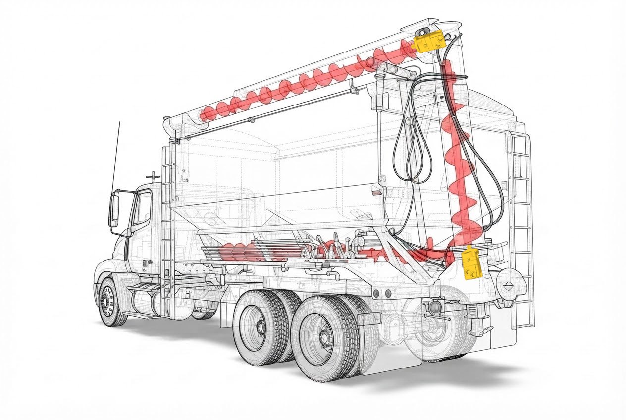
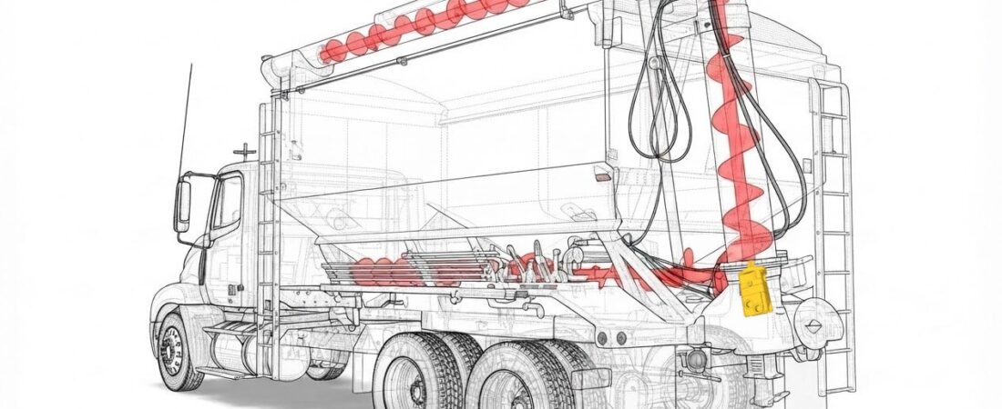
The unloading auger on a bulk grain and feed truck is one of the applications THOTH lists for its BM3Y motor.ZI-2 Each unload runs for several minutes without stopping, has to start with the auger packed full of grain, and works outdoors in heavy dust. Almost every factor that matters in low-speed, high-torque motor selection shows up in this one job.
We’ll use it to walk through the selection process from start to finish.
NoteThe load and circuit conditions in this article are assumed values used to illustrate the design process, not a specific customer case. All motor data are THOTH catalog values.
Define the requirement in numbers
Selection starts with the machine, not the motor. These are the conditions assumed for this article.
| Parameter | Assumed value | What it means |
|---|---|---|
| Running torque | 380 N·m | Torque needed continuously while grain is flowing |
| Auger speed | 230 rpm | Sets the unloading rate |
| Start-up torque | 550 N·m (seconds) | Starting with the auger packed full of grain |
| Duty pattern | 10–15 min continuous | No pauses during an unload, judged against the continuous rating |
| Power source | PTO gear pump, 60 L/min | Upper limit on the flow available to the motor |
| Return back pressure | ≈ 1 MPa | Pressure at the motor outlet, reduces the usable pressure differential |
| Environment | Outdoor, grain dust | Shared with the supplier together with the duty data |
In a real design, it’s better to measure these numbers than estimate them. If an existing machine is available, gauge the motor inlet and outlet pressures during unloading, then apply that differential to the catalog performance grid to back-calculate the torque actually required.
Filter candidates on continuous and intermittent ratings
The THOTH catalog lists continuous, intermittent, and peak ratings separately for every model. Intermittent operation is allowed for up to 10% of every minute (6 seconds); peak for only 1% (0.6 seconds).ZI-1 That sets the criteria:
- Running torque of 380 N·m at 230 rpm must sit inside the continuous rating.
- Start-up torque of 550 N·m lasts only seconds, so it only needs to sit inside the intermittent rating. We don’t design on the peak rating.
Continuous vs. intermittent torque
Six candidate models, N·m
| Candidate | Cont. torque | Int. torque | Cont. max speed | Weight | Verdict |
|---|---|---|---|---|---|
| BMR-250 | 395 | 470 | 235 | 8.5 kg | OutStart-up torque short; almost no speed margin |
| BMRY-200 | 455 | 520 | 295 | 8.0 kg | OutCan’t reach 550 intermittent |
| BMRY-250 | 470 | 540 | 235 | 8.5 kg | OutStart-up torque short |
| BM3Y-160 | 451 | 559 | 465 | 10.7 kg | HoldOnly 2% start-up margin |
| BM3Y-200 | 564 | 672 | 370 | 11.1 kg | Pass |
| BM4-200 | 561 | 714 | 495 | 20.8 kg | Pass |
The axial-drain BMR and BMRY families handle the running torque but fail at start-up, in this application, start-up torque is the first gate. What remains is the end-face-drain BM series, which is built around high start-up torque, a wide speed range, and direct low-speed, heavy-load drive of the working implement.ZI-1
Check whether you need a gearbox
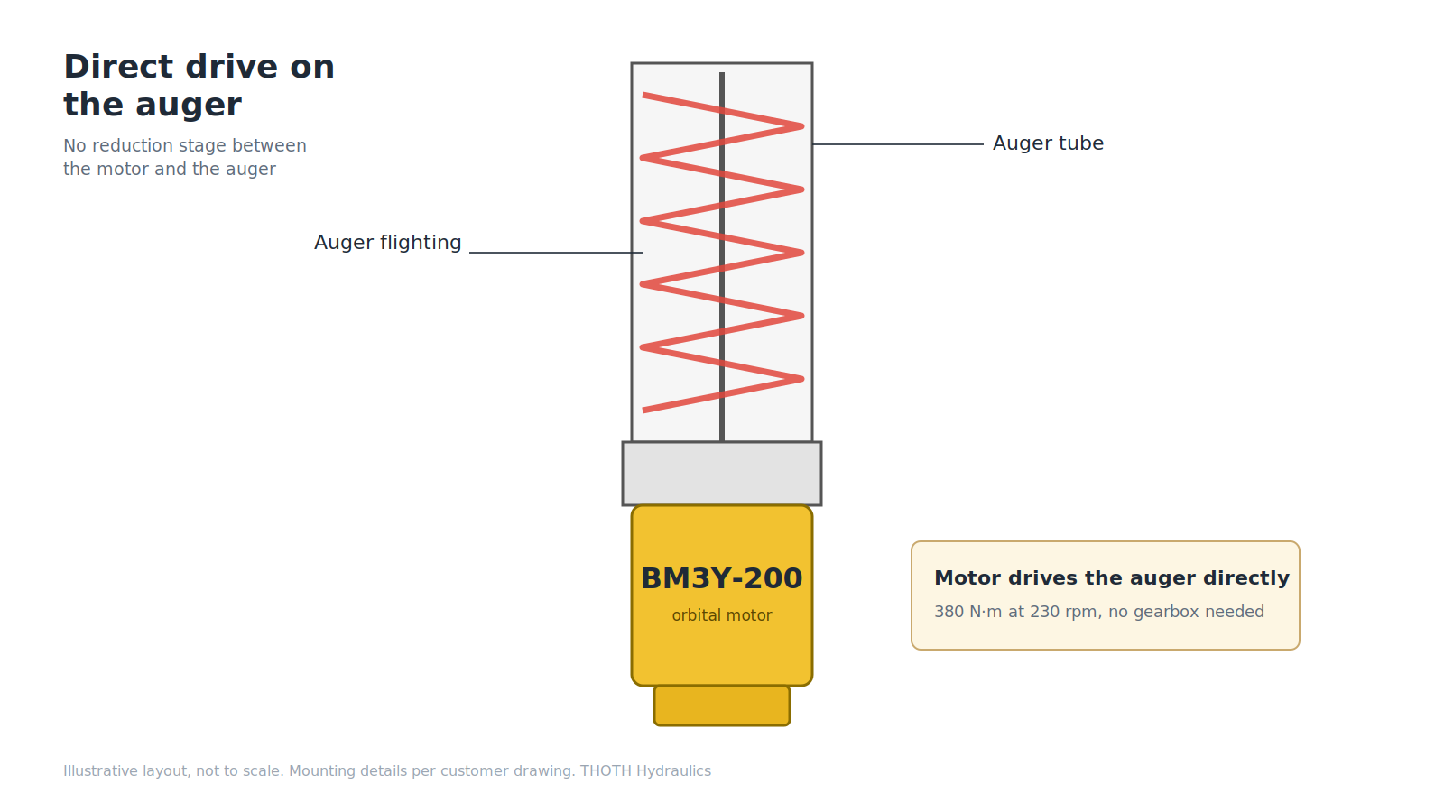
The duty point of 380 N·m at 230 rpm sits inside the BM3Y-200’s continuous envelope (564 N·m, 370 rpm), and an unloading auger does not need to hold a load at standstill. The motor can drive the auger directly, without a reduction stage.
A gearbox is worth considering when the required torque exceeds the orbital motor’s continuous range, when the speed is very low, or when the load must be held at standstill.
Place the duty point on the performance grid
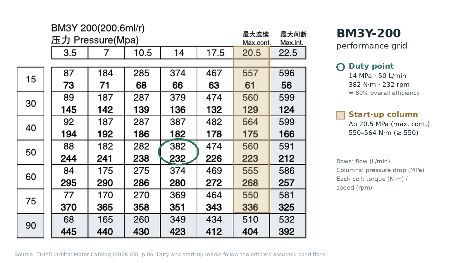
Now compare the two remaining BM3Y sizes on their performance grids. Each cell gives the actual torque and speed at that pressure and flow, so find the cell closest to the duty point and calculate its efficiency.ZI-1
Why divide by 2π? Displacement × pressure differential is the work done per revolution. Torque is work per radian, and one revolution is 2π radians.
| BM3Y-200 | BM3Y-160 | |
|---|---|---|
| Nearest grid cell | 14 MPa · 50 L/min → 382 N·m, 232 rpm | 17.5 MPa · 40 L/min → 386 N·m, 222 rpm |
| Overall efficiency (calc.) | ≈ 80% | ≈ 77% |
| Flow needed vs. 60 L/min pump | ≈ 50 L/min, margin available | ≈ 41 L/min, large margin |
| Running Δp / cont. rating | 14 / 20.5 MPa | 17.5 / 20.5 MPa |
On the BM3Y-200, the duty point lands in the middle of the grid. A 14 MPa differential is about 70% of the continuous rating, leaving headroom on oil temperature and seal load, and efficiency is slightly higher. The BM3Y-160 uses less flow, but runs permanently at 85% of its continuous pressure rating. In a job that runs without pause, that difference turns into heat, and into service life.
Check start-up torque on the grid
Start-up torque is higher than running torque: the motor has to break the auger free from rest with the flights packed full of grain. On the BM3Y-200 grid, the cells delivering 550 N·m or more sit in the 20.5 MPa column (550–564 N·m).ZI-1 So the circuit must be able to deliver about 20.5 MPa across the motor for a packed auger to start.
That is within the BM3Y-200’s 25 MPa intermittent pressure rating, and a start lasts only seconds, well inside the intermittent limit of 6 seconds per minute.ZI-1
Why the BM3Y-160 drops out. Its grid gives only about 480 N·m even at 22.5 MPa, short of 550. It would have to run toward the end of its intermittent rating just to start, with no margin left.ZI-1
Decide on the motor
The BM3Y-200 and BM4-200 both pass, but they weigh 11.1 kg and 20.8 kg, almost a factor of two.ZI-1 For a motor mounted on the end of an auger, the lighter one puts less load on the structure. The BM4-200 can take up to 100 L/min, so it stays on the list if you plan to raise the unloading rate substantially or want more torque margin.
BM3Y-200, direct drive
Alternative · BM4-200
It reaches the start-up torque within its intermittent range, puts the duty point in the middle of the grid (14 MPa differential, about 80% efficiency), works within the pump’s 60 L/min, and is the lighter of the two passing candidates.
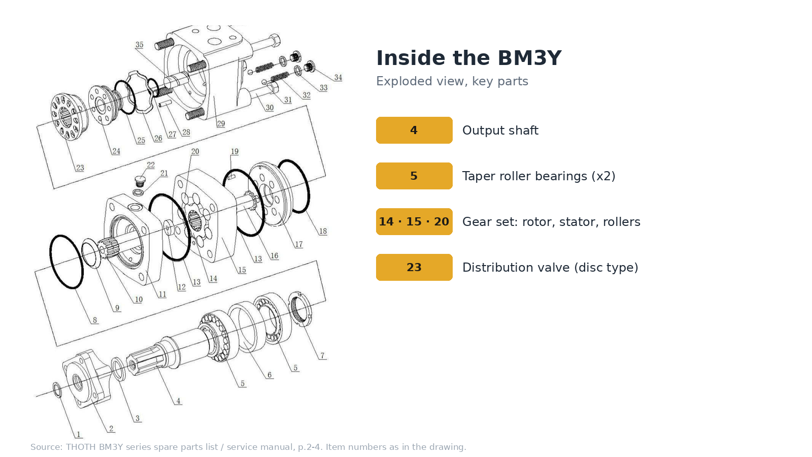
NextShaft, flange and port options are set by the order code and confirmed against the customer’s drawing.
Good selection isn’t choosing a big motor. It’s choosing the right one.
Turn the requirement into numbers, filter on continuous and intermittent ratings, confirm the duty point on the performance grid and check start-up torque, and the decision narrows naturally to one.
Send us your operating conditions,
we’ll run the same six steps.
Running and start-up torque, speed, duty time, pump flow and pressure. THOTH will review them in the same order and come back with a proposed configuration. Standard lead time is 3–4 weeks.ZI-2
- ZI-1ZIHYD Orbital Motor Catalog (2026.03). BMR p.37, BMRY p.38, BM series overview p.83, BM3Y technical parameters p.84 and performance grids p.85–86, BM4 p.102, intermittent and peak operation definitions.
- ZI-2THOTH / ZiHYD company profile (2025). Applications (grain truck unloading: BM3Y); supply terms (standard lead time).
- ZI-3THOTH BM3Y series spare parts list / service manual. Exploded view and parts list, p.2–4.